The graph data structure of Mastodon.
The mastodon-graph Java package can be used to implement directed graphs with small memory footprint.
Vertices and edges are not stored as individual objects. Instead vertex and edge data is laid out in a primitive byte[] array and accessed via proxy objects.
This page describes some internals of the trackmate-graph package.
Memory layout.
Each vertex and each edge maps to a contiguous portion of a byte[] array.
The size of a portion (elements) is fixed for a particular AbstractVertex or AbstractEdge subclass.
Each element starts with a fixed part that represents the graph structure and then additional payload used by the subclass to describe some vertex attributes, etc.
There is one byte[] array that stores all vertices, and one byte[] array that stores all edges.
References between these arrays are in the form of element indices.
Whether these are indices refer to elements in the vertex or in the edge memory array is clear from the context.
Vertex layout.
The following diagram illustrates the layout of vertices in a byte[] array:
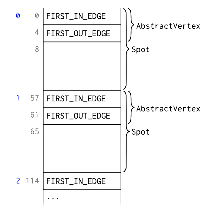
In the left-most column, element indices are shown (in blue), followed by byte indices (in grey). In the example, each element of the AbstractVertex subclass Spot requires 57 bytes to store.
The data for the i th Spot starts at byte i * 57.
The fixed AbstractVertex part comprises element indices FIRST_IN_EDGE and FIRST_OUT_EDGE, occupying 4 bytes each.
The remaining 49 bytes are Spot attributes.
FIRST_IN_EDGE is the element index (in the edge memory array) of the first incoming edge, i.e., an edge pointing to this vertex.
The remaining incoming edges of the same vertex are stored as a linked list in the edge memory as described below.
If this vertex does not have any incoming edges FIRST_IN_EDGE is -1.
Similarly, FIRST_OUT_EDGE is the element index of the first outgoing edge, i.e., an edge starting from this vertex.
The remaining outgoing edges of the same vertex are stored as a linked list in the edge memory as described below. If this vertex does not have any outgoing edges
FIRST_OUT_EDGE is -1.
Edge layout.
The following diagram illustrates the layout of edges in a byte[]
array:
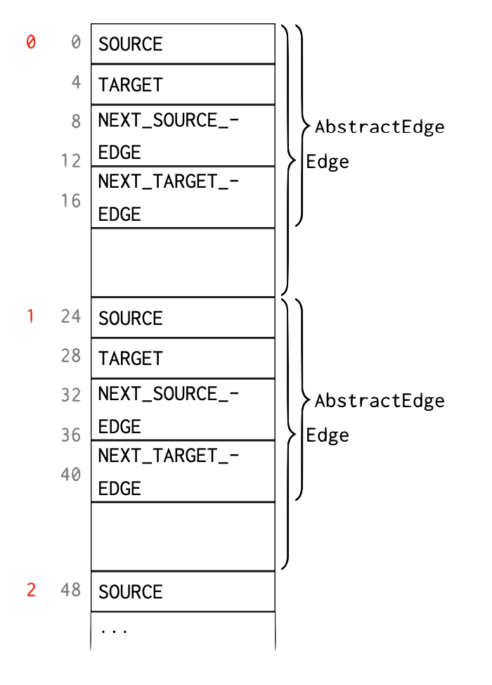
In the left-most column, element indices are shown (in red), followed by byte indices (in grey). In the example, each element of the AbstractEdge subclass Edge requires 24 bytes to store.
The data for the i th Edge starts at byte i * 24.
The fixed AbstractEdge part comprises element indices SOURCE, TARGET, NEXT_SOURCE_EDGE, and NEXT_TARGET_EDGE, occupying 4 bytes each.
The remaining 8 bytes are Edge attributes.
SOURCEis the element index (in the vertex memory array) of the vertex from which this edge starts.TARGETis the element index (in the vertex memory array) of the vertex to which this edge points.NEXT_SOURCE_EDGEis the element index (in the edge memory array) of the next outgoing edge of the source vertex, , the next edge that has the sameSOURCE. If there is no such edge thenNEXT_SOURCE_EDGEis -1.NEXT_TARGET_EDGEis the element index (in the edge memory array) of the next incoming edge of the target vertex, , the next edge that has the sameTARGET. If there is no such edge thenNEXT_TARGET_EDGEis -1.
Example
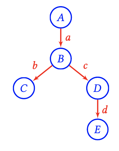
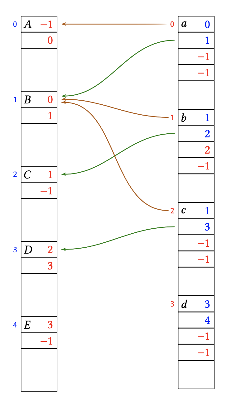
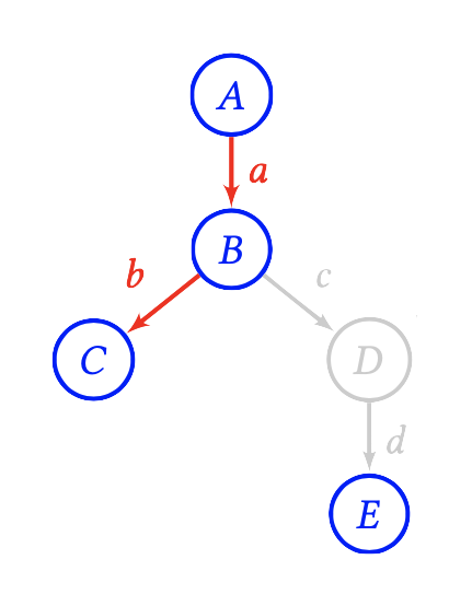
Consider the following example graph comprising vertices A, B, C, D, E and edges a, b, c, d.
This is laid out in memory as follows
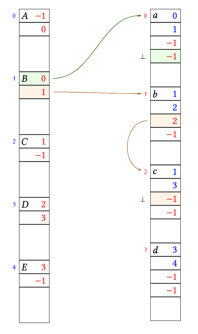
The links between vertex B and its adjacent edges a, b, c have been highlighted.
Let’s look at that in more detail:
Vertex B is stored at element index 1 in the vertex memory array.
B has one incoming edge a.
The edge a is stored at element index 0 in the edge memory array.
Therefore the FIRST_IN_EDGE field of B is 0.
Apart from a, the vertex B has no further incoming edges.
Therefore, the NEXT_TARGET_EDGE field of a is -1, i.e., the list of edges entering B terminates here.
B has two outgoing edges b, c.
The edge b is stored at element index 1 in the edge memory array.
Therefore the FIRST_OUT_EDGE field of B is 1.
The next outgoing edge of B is c which is stored at element index 2.
Therefore, the NEXT_SOURCE_EDGE field of b is 2.
After c, the vertex B has no further outgoing edges.
Therefore, the NEXT_SOURCE_EDGE field of c is -1, i.e., the list of edges leaving B terminates here.
Below is the same memory layout again, this time highlighting the references from edges a, b, c back to the vertex memory array.
For example, edge c is leaving vertex B (index 1) and entering vertex D (index 3).
Therefore the SOURCE field of c is 1, and the TARGET field of c is 3.
Free-list of unallocated elements.
The vertex and edge memory arrays can only ever grow. When elements are released, they are simply marked as free for re-use. Assume that in the above example vertex D is deleted, as well as it’s adjacent edges c, d, leaving this:
After removing c, d, D the memory layout looks like this:
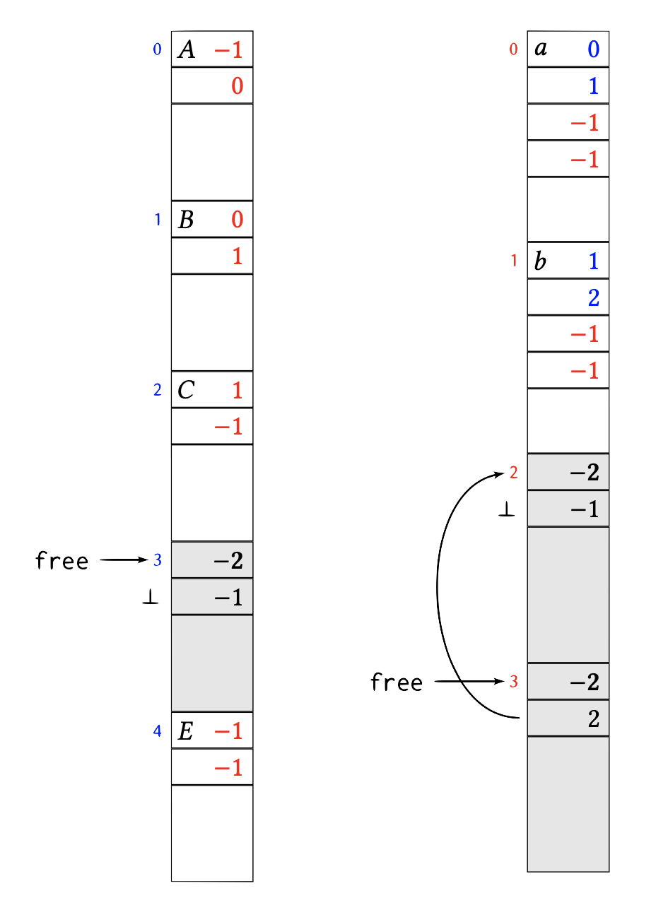
The element 3 in the vertex memory array as well as elements 2 and 3 in the edge memory array have been marked as free.
This is done by putting the magic number “-2” into the first 4 bytes of the element.
In vertices and edges the first 4 bytes are always occupied by a (positive) index or a −1 index list terminator.
Therefore, occupied and free blocks cannot be confused.
The next 4 bytes of a freed element are the index of the next freed element in the (same) memory array, or -1 if there is no next freed element.
Each memory array remembers the index free of the first freed element.
Newly freed elements are enqueued at free, that is, at the head of the free-list.
So in the above example, edge element 2 was freed first, followed by edge element 3.
The next edge element will be allocated at head of the free-list and the free index move to the next element.
For example, assume that a new edge is created from B to E:
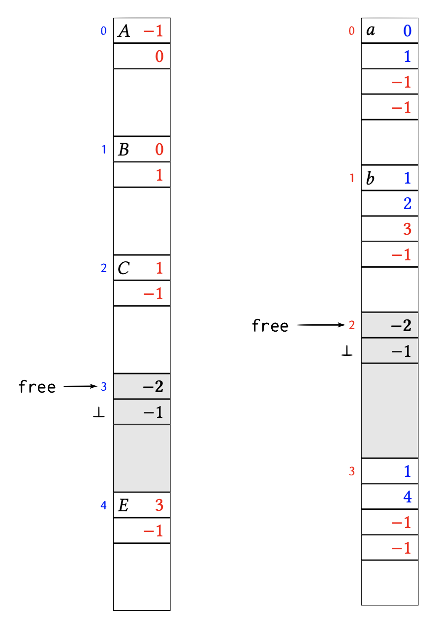
If free is -1, then no more freed elements are available and the underlying memory array has to grow to fit newly added elements.